FINAL YEAR PROJECT

BLINDSPOT WARNING AND SPEED MANIPULATION BY DATA TRANSFER THROUGH CAN PROTOCOL
TEAM MEMBERS:
- Mr. S. Amruth, Department Of ECE, amruthsrku@gmail.com, SMKFIT, Chennai.
- Mr. J. Eyanaeswhararaj, Department Of ECE, eyanaeswh@gmail.com, SMKFIT, Chennai.
- Mr. M. Hemantha Kumar, Department Of ECE, hemanthakumar8899@gmail.com, SMKFIT, Chennai.
- Mr. P.Ajith Kumar Department Of ECE, ajith270916@gmail.com, SMKFIT, Chennai.
To view the full Report: Click Here.
ABSTRACT
The motive of our project is to mitigate the number of road accidents by making the vehicles communicate among themselves by transferring the data using CAN protocol. Speed of the adjacent vehicle is captured via the wireless transceiver and logged into a dedicated Electronic control unit. The concerned vehicle's speed is sensed and captured. The ultrasonic sensors detect the presence of obstacle or vehicles residing in the region of blind spot, all this information are logged in to the ECU and transferred from one vehicle to an adjacent vehicle using CAN protocol. CAN protocol involves communication between various controllers without the involvement of a host computer which finds a wide application in the automotive industry. Thus, the proneness of accidents is greatly avoided which in turn pulls down the accident rate thereby saving more lives.
INTRODUCTION
Theoretical Background:
Every day we are communicating with each other in some way or another, be it by using words, actions, or even expressions in conveying a message. We, humans, depend not only on face-to-face communication but the kind that brings technology to the fore to bridge that gap between people by mere seconds across vast distances.
In The 5th Century, Letters And Documents Could Be Sent By using Pigeons’ Homing Abilities. Pigeons were trained by being removed from their homes and taken to a destination, from which they would return home. Observation stations were built on a hilltop to relay these messages over long distances One of the NSA’s observatory stations at Teufelsberg. These networks were replaced by telegraph networks invented by “Samuel morse” in 1838. Marconi-Radio's ability-first wireless telegraphy in 1897 was used to send one-way signals. Alexander Graham Bell, who patented the telephone, inaugurated the 1,520- km telephone line. After the invention of mobile phones till the 20th-century mobile were made to access only for voice and SMS usage.
In the 21st century smartphones were the biggest evolution created in telecommunications We have seen a drastic changeover in communicational technologies and in our lifestyles too. There is no point in that, it doesn’t take much time for us to convert from 4G to 5G and is much more advanced. Only the thing is how ethically we are perfectly synchronized with the technology in our livelihoods. Ongoing in advance, inventors try to develop a technology that can make the machines communicate with each other. Thus in the case of automobile industries, the evolution of Vehicle to vehicle communication came into existence.
The evolution of the technologies and the standards enables a vehicle to communicate with other vehicles and the surrounding environment and become part of an extended intelligent transportation system (ITS) communication system able to support a wide range of services by using different communication media.
V2V Communication:
Vehicle-to-vehicle communication (V2V communication) is the wireless transmission of data between motor vehicles. The goal of V2V communication is to prevent accidents by allowing vehicles in transit to send position and speed data to one another over an ad-hoc mesh network. Depending upon how the technology is implemented, the vehicle's driver may simply receive a warning should there be a risk of an accident, or the vehicle itself may take preemptive actions such as braking to slow down. V2V communication is expected to be more effective than current automotive original equipment manufacturer (OEM) embedded systems for lane departure, adaptive cruise control, blind-spot detection, rear parking sonar, and backup camera because V2V technology enables a ubiquitous 360-degree awareness of surrounding threats. V2V communication is part of the growing trend towards pervasive computing, a concept known as the Internet of Things (IoT). In the United States, V2V is an important part of the intelligent transport system (ITS), a concept that is being sponsored by the United States Department of Transportation (DOT) and the National Highway Traffic Safety Administration (NHTSA).
The implementation of V2V communication and an intelligent transport system currently has three major roadblocks: the need for automotive manufacturers to agree upon standards, data privacy concerns, and funding. As of this writing, it is unclear whether the creation and maintenance of the supporting network would be publicly or privately funded. Automotive manufacturers working on ITS and V2V include GM, BMW, Audi, Daimler, and Volvo.
EXISTING SYSTEM Communication between vehicles is established using short-range communication (SRC). The conventional system works based on the accelerator input, the rate of fuel flow given to the engine, and the speed is controlled accordingly. If the vehicle needs to run at high speed the accelerator pedal has to be pressed more so that it supplies more fuel to the engine. In this method, the driver's concentration is much more and always alert to take necessary control actions depending on the traffic situation.
Fig: calculation of gap distance to avoid collisionSome of the hardware components in-vehicle can be integrated into a single unit or a discrete set of components and consist of the following component,1) Dedicated Short Range (DSRC) radio: Responsible for receiving and transmitting data over antennae.2) GPS Receiver: Provides the vehicle position, time to DSRC radio, and timing signals for applications.3) Memory: Responsible for storing the security certificates with other information and application data.4) DSRC & GPS Antenna: Interface between the propagating radio waves and its responsible for receiving and transmitting both the DSRC and GPS signals. Fig: Block Diagram of the existing system
Disadvantages of Existing System:
The existing system even though very useful, also has several disadvantages like• Drivers concentration is much more and always alert to take necessary control actions depending on the traffic situation.• Increases cost of vehicle and maintenance.• User’s Ignorance.• The overall collision avoidance system is controlled manually.
PROPOSED SYSTEM In our proposed system, the vehicles are granted to communicate and share data via wireless transceiver by using CAN protocol. Speed of the adjacent vehicle and blind-spot warning information are communicated via Zigbee to the adjacent vehicle and are logged into a dedicated Electronic control unit (ECU). Vehicle at the blind spot region can be identified using ultrasonic sensors. An emergency electronic braking system provides automatic deceleration of vehicles to avoid a collision. The alert message passes from one node controller to another. Each autonomous and mobile node, connected to the others, forms a partially connected mesh network. The individual nodes forward the packets to each other. Improve the performance by making all the vehicles close to interact with each other and help the car in danger to undertake a more effective choice to solve the emerging problem.  Fig: Block Diagram of Vehicle 1
 Fig: Block Diagram of Vehicle 2
The new Intelligent Transport Systems (ITSs) will employ data from V2V communication to enhance traffic management, allowing vehicles to also communicate with road infrastructures, such as traffic lights or signs. These technologies could become mandatory in the not too distant future and contribute to building more reliable self-driving cars on motorways. The proposed system comprises of performing the following works:
1. Collision avoidance2. Collision detection3. Blind spot warning
To view the full Report: Click Here.
1. COLLISION AVOIDANCE The collision avoidance system involves the usage of Speed sensors to detect the speed of the adjacent vehicle. The obtained data is then fed into the ECU of the car unit and the ECU is connected with the Zigbee for transferring the data using CAN protocol. Depending on the obtained data the speed of the corresponding vehicle which receives the data is decelerated by reducing the motor speed. Such that the proneness to accidents can be avoided.2. COLLISION DETECTION The collision detection mechanism involves passing the message from one car node to another when one car gets involved in an accident or collision. CAN protocol is used to communicate these messages from one node to another. Fig: Process of Speed Manipulation
3 BLIND SPOT WARNING This unit is concentrated separately because most of the accidents occur when the driver could not able to see the object which is nearer to the vehicle. The region which is not been visualized to the driver is known as the blind spot. The objects or vehicles which is present in the region of the blind spot are identified using ultrasonic sensors. The sensor data is then loaded in ECU for transferring the data to the adjacent vehicle.  Fig: Process of Blindspot warning
Advantages of Proposed system:
• CAN protocol is resilient to electrical noise.• CAN protocol implementation requires low cost.• Blind spot warning.• Can communicate with more number of vehicles.• Every operation will be controlled automatically.• Automatic braking system.
HARDWARE MODEL
WORKING PRINCIPLE Different ECUs can communicate with each other via CAN Bus. The input speed of the vehicle is given through the speed switch to the ECU2 of vehicle 1. The motor rotates according to the speed (rpm) applied on the switch. The obtained speed is then communicated to the ECU1 via CAN Bus. The ECU 1 contains the Zigbee module which transmits the obtained information to the adjacent vehicle(Vehicle 2) Then the speed of the motor in vehicle 2 is manipulated according to the speed of vehicle 1. The Buzzer is used to indicate sound during speed manipulation. The ultrasonic sensor is used to identify the objects in the region of the blind spot. If there is any object or vehicle below the range of 20cm, the buzzer is ON and an alert message is passed from vehicle 1 to vehicle 2. Then vehicle 2 can pass an acknowledge message like1. Wait do not overtake.2. Yes you can overtakeThe same process is repeated in vehicle 2.

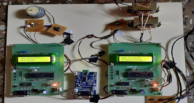 Fig: Images of the Developed Model
To view the full Report: Click Here.
SOFTWARE REQUIREMENTS:1. Embedded c2. Mp lab IDEHARDWARE REQUIREMENTS:1. PIC 18F4852. MCP2551 CAN Transceivers.3. Zigbee module4. Speed switch5. Motor driver and motor6. LCD7. Ultrasonic sensor8. Buzzer
CONCLUSION To avoid accidents and collisions many types of experiments are conducted. Thus, in a nutshell, vehicle safety and communication between vehicles have been conceived based on the CAN protocol. It is an emerging technology that may be predominant and will come into existence may be within a decade. Yet, still, the further edification of these systems is possible such asi. The collected data can be uploaded on a centralized server for ease of access.ii. Encryption on the CAN messages can help secure the communication over the CAN bus.iii. On a large scale, the system may also employ RTOS.
It’s evident that technology has great capabilities to help future generation transportation systems. V2V communication has unique characteristics to enable future generation intelligent transportation systems. We are planning to provide a few safety applications through our proposed system in order to provide efficient output at a reliable cost.
To view the full Report: Click Here.
REFERENCES[1] Mayur Shinde, Nidhi Pandey, Pritham Shetty, Harsh Umrania &Prof.Manoj Mishra, International Conference on Innovative and Advanced Technologies in Engineering (March-2018)[2] Xiuliang Mo1,2, Pengyuan Chen1,2(B), Jianing Wang3, and Chundong Wang1,2 2 Tianjin Key Laboratory of Intelligence Computing and Novel Software Technology, Ministry of Education, Tianjin University of Technology, Tianjin 300384, China 3 Sichuan University, Chengdu 610207, Sichuan, China[3] Hussain A. Attia*, Shereen Ismail&, Halah Y. Ali# *Department of Electrical, Electronics and Communications Engineering / School of Engineering & Department of Computer Science and Engineering / School of Engineering #Department of Biotechnology / School of Art and Science American University of Ras Al Khaimah, Ras Al Khaimah, UAE.[4] Nurbaiti Wahid, 2Hairi Zamzuri, 2Mohd Azizi Abdul Rahman, 3Satoshi Kuroda, 3Pongsathorn Raksincharoensak ,Nakacho 2-24-16, Koganei, Tokyo 184-8588, Japan,IEEE 2017.[5] Erçakır, O.; Kızılırmak, O.; Erol, V. Network Security Issues and Solutions on Vehicular Communication Systems. Preprints 2017, 2017060001doi:10.20944/preprints201706.0001.v1[6] M. T. Wolf and J. W. Burdick, “Artificial potential functions for highway driving with collision avoidance,” in Robotics and Automation, 2008. ICRA 2008.IEEE International Conference on. IEEE, 2008, pp. 3731– 3736.[7] E. Nasr, E. Kfoury and D. Khoury, "An IoT approach to vehicle accident detection, reporting, and navigation," 2016 IEEE International MultidisciplinaryConference on Engineering Technology (CET), Beirut, 2016, pp. 231-236.[8] LORA: Loss Differentiation Rate Adaptation Scheme for Vehicle-to-Vehicle Safety Communications Yuan Yao, Member, IEEE, Xi Chen, Student Member, IEEE, Lei Rao, Member, IEEE, Xue Liu, Member, IEEE, and Xingshe Zhou, Member, IEEE,2016 IEEE.[9] Weil, T.: VPKI Hits the Highway: Security Communication for the Connected Vehicle Program. IT Professional Magazine, Vol. 19, Issue 1, pp.59-63, 2017.[10] S. Pallewatta, P. S. Lakmali, S. Wijewardana, P. Ranathunga,T.Samarasinghe,andD.Dias,“802.11p: Insights from the MAC and physical layers for a cooperate car following application,” in Proc. EAI International Conference on Intelligent Transport Systems, pp. 226–236, Jul. 2018.
To view the full Report: Click Here.
Communication between vehicles is established using short-range communication (SRC). The conventional system works based on the accelerator input, the rate of fuel flow given to the engine, and the speed is controlled accordingly. If the vehicle needs to run at high speed the accelerator pedal has to be pressed more so that it supplies more fuel to the engine. In this method, the driver's concentration is much more and always alert to take necessary control actions depending on the traffic situation.
Fig: calculation of gap distance to avoid collision
Some of the hardware components in-vehicle can be integrated into a single unit or a discrete set of components and consist of the following component,
1) Dedicated Short Range (DSRC) radio: Responsible for receiving and transmitting data over antennae.
2) GPS Receiver: Provides the vehicle position, time to DSRC radio, and timing signals for applications.
3) Memory: Responsible for storing the security certificates with other information and application data.
4) DSRC & GPS Antenna: Interface between the propagating radio waves and its responsible for receiving and transmitting both the DSRC and GPS signals.
Fig: Block Diagram of the existing system
Disadvantages of Existing System:
The existing system even though very useful, also has several disadvantages like
• Drivers concentration is much more and always alert to take necessary control actions depending on the traffic situation.
• Increases cost of vehicle and maintenance.
• User’s Ignorance.
• The overall collision avoidance system is controlled manually.
PROPOSED SYSTEM
In our proposed system, the vehicles are granted to communicate and share data via wireless transceiver by using CAN protocol. Speed of the adjacent vehicle and blind-spot warning information are communicated via Zigbee to the adjacent vehicle and are logged into a dedicated Electronic control unit (ECU). Vehicle at the blind spot region can be identified using ultrasonic sensors. An emergency electronic braking system provides automatic deceleration of vehicles to avoid a collision. The alert message passes from one node controller to another. Each autonomous and mobile node, connected to the others, forms a partially connected mesh network. The individual nodes forward the packets to each other. Improve the performance by making all the vehicles close to interact with each other and help the car in danger to undertake a more effective choice to solve the emerging problem.
Fig: Block Diagram of Vehicle 1
The new Intelligent Transport Systems (ITSs) will employ data from V2V communication to enhance traffic management, allowing vehicles to also communicate with road infrastructures, such as traffic lights or signs. These technologies could become mandatory in the not too distant future and contribute to building more reliable self-driving cars on motorways. The proposed system comprises of performing the following works:
1. Collision avoidance
2. Collision detection
3. Blind spot warning
To view the full Report: Click Here.
1. COLLISION AVOIDANCE The collision avoidance system involves the usage of Speed sensors to detect the speed of the adjacent vehicle. The obtained data is then fed into the ECU of the car unit and the ECU is connected with the Zigbee for transferring the data using CAN protocol. Depending on the obtained data the speed of the corresponding vehicle which receives the data is decelerated by reducing the motor speed. Such that the proneness to accidents can be avoided.
2. COLLISION DETECTION The collision detection mechanism involves passing the message from one car node to another when one car gets involved in an accident or collision. CAN protocol is used to communicate these messages from one node to another.
Fig: Process of Speed Manipulation
3 BLIND SPOT WARNING This unit is concentrated separately because most of the accidents occur when the driver could not able to see the object which is nearer to the vehicle. The region which is not been visualized to the driver is known as the blind spot. The objects or vehicles which is present in the region of the blind spot are identified using ultrasonic sensors. The sensor data is then loaded in ECU for transferring the data to the adjacent vehicle.
Fig: Process of Blindspot warning
Advantages of Proposed system:
• CAN protocol is resilient to electrical noise.
• CAN protocol implementation requires low cost.
• Blind spot warning.
• Can communicate with more number of vehicles.
• Every operation will be controlled automatically.
• Automatic braking system.
HARDWARE MODEL
WORKING PRINCIPLE
Different ECUs can communicate with each other via CAN Bus. The input speed of the vehicle is given through the speed switch to the ECU2 of vehicle 1. The motor rotates according to the speed (rpm) applied on the switch. The obtained speed is then communicated to the ECU1 via CAN Bus. The ECU 1 contains the Zigbee module which transmits the obtained information to the adjacent vehicle(Vehicle 2) Then the speed of the motor in vehicle 2 is manipulated according to the speed of vehicle 1. The Buzzer is used to indicate sound during speed manipulation. The ultrasonic sensor is used to identify the objects in the region of the blind spot. If there is any object or vehicle below the range of 20cm, the buzzer is ON and an alert message is passed from vehicle 1 to vehicle 2. Then vehicle 2 can pass an acknowledge message like
1. Wait do not overtake.
2. Yes you can overtake
The same process is repeated in vehicle 2.
To view the full Report: Click Here.
SOFTWARE REQUIREMENTS:
1. Embedded c
2. Mp lab IDE
HARDWARE REQUIREMENTS:
1. PIC 18F485
2. MCP2551 CAN Transceivers.
3. Zigbee module
4. Speed switch
5. Motor driver and motor
6. LCD
7. Ultrasonic sensor
8. Buzzer
CONCLUSION
To avoid accidents and collisions many types of experiments are conducted. Thus, in a nutshell, vehicle safety and communication between vehicles have been conceived based on the CAN protocol. It is an emerging technology that may be predominant and will come into existence may be within a decade. Yet, still, the further edification of these systems is possible such as
i. The collected data can be uploaded on a centralized server for ease of access.
ii. Encryption on the CAN messages can help secure the communication over the CAN bus.
iii. On a large scale, the system may also employ RTOS.
It’s evident that technology has great capabilities to help future generation transportation systems. V2V communication has unique characteristics to enable future generation intelligent transportation systems. We are planning to provide a few safety applications through our proposed system in order to provide efficient output at a reliable cost.
To view the full Report: Click Here.
REFERENCES
[1] Mayur Shinde, Nidhi Pandey, Pritham Shetty, Harsh Umrania &
Prof.Manoj Mishra, International Conference on Innovative and Advanced Technologies in Engineering (March-2018)
[2] Xiuliang Mo1,2, Pengyuan Chen1,2(B), Jianing Wang3, and Chundong Wang1,2 2 Tianjin Key Laboratory of Intelligence Computing and Novel Software Technology, Ministry of Education, Tianjin University of Technology, Tianjin 300384, China 3 Sichuan University, Chengdu 610207, Sichuan, China
[3] Hussain A. Attia*, Shereen Ismail&, Halah Y. Ali# *Department of Electrical, Electronics and Communications Engineering / School of Engineering & Department of Computer Science and Engineering / School of Engineering #Department of Biotechnology / School of Art and Science American University of Ras Al Khaimah, Ras Al Khaimah, UAE.
[4] Nurbaiti Wahid, 2Hairi Zamzuri, 2Mohd Azizi Abdul Rahman, 3Satoshi Kuroda, 3Pongsathorn Raksincharoensak ,Nakacho 2-24-16, Koganei, Tokyo 184-8588, Japan,IEEE 2017.
[5] Erçakır, O.; Kızılırmak, O.; Erol, V. Network Security Issues and Solutions on Vehicular Communication Systems. Preprints 2017, 2017060001doi:10.20944/preprints201706.0001.v1
[6] M. T. Wolf and J. W. Burdick, “Artificial potential functions for highway driving with collision avoidance,” in Robotics and Automation, 2008. ICRA 2008.
IEEE International Conference on. IEEE, 2008, pp. 3731– 3736.
[7] E. Nasr, E. Kfoury and D. Khoury, "An IoT approach to vehicle accident detection, reporting, and navigation," 2016 IEEE International Multidisciplinary
Conference on Engineering Technology (CET), Beirut, 2016, pp. 231-236.
[8] LORA: Loss Differentiation Rate Adaptation Scheme for Vehicle-to-
Vehicle Safety Communications Yuan Yao, Member, IEEE, Xi Chen, Student Member, IEEE, Lei Rao, Member, IEEE, Xue Liu, Member, IEEE, and Xingshe Zhou, Member, IEEE,2016 IEEE.
[9] Weil, T.: VPKI Hits the Highway: Security Communication for the Connected Vehicle Program. IT Professional Magazine, Vol. 19, Issue 1, pp.
59-63, 2017.
[10] S. Pallewatta, P. S. Lakmali, S. Wijewardana, P. Ranathunga,T.
Samarasinghe,andD.Dias,“802.11p: Insights from the MAC and physical layers for a cooperate car following application,” in Proc. EAI International Conference on Intelligent Transport Systems, pp. 226–236, Jul. 2018.
To view the full Report: Click Here.


0 comments:
Post a Comment